 Airfoil Data : Airfoil Data :
Subsonic Characteristics
Overview
Airfoil sections are widely available. They generally are based on data from various research establishments such as the old NACA (now NASA) and, more recently, from universities. Many CAD programs have copied the NACA formula for the "four digit" sections developed in the early 1930's and draw airfoils based on it.
These section data follow normal aircraft practice. The airfoil coordinates are given relative to a reference line that is drawn from the trailing edge to the most forward part of the leading edge. This is done to keep the upper coordinates all positive and the lower coordinates all negative. Airfoil data measured in wind tunnels and quoted in most places are referenced to this line.
Pitch gauges used in model aircraft practice, on the other hand, do not work this way. They measure to the bottom of the airfoil. In a flat bottom section this is easy to understand. For a symmetrical section, for instance, the angles measured depend on technique and are not clearly defined. For the common flat bottomed section or undercambered sections in which the pitch gauge has two well-defined points to rest on the angel for pitch measurement is well defined, and it is not to the reference line of the airfoil. Because of this, airfoil data must be reinterpreted for model aircraft prop design so measured pitch will correspond to some known airfoil reference.
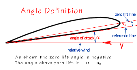
The general effect is to make the measured pitch correspond to a line below the airfoil reference line. This makes the "angle of zero lift" relative to the line measured by the pitch gauge more negative. See the drawing below to see the system that must be used to make calculations work out with a pitch gauge.

Airfoil angles that are used are referred to the system shown on the right. This is a 'model builder system' in that the reference line is the line that will be used with a pitch gauge or other angle measuring device. The 'angle of attack' in this program is measured from the reference line to the oncoming airstream. As shown in the drawing it is positive. The zero lift angle is measured from the reference line to the relative wind direction that produces no lift. As shown in the drawing it is negative. This angle would be zero for a symmetrical airfoil. The angle above zero lift that is entered is the difference of the angle of attack and the angle of zero lift. A typical airfoil in a model aircraft propeller might have a zero lift angle relative to the pitch gauge of -6 deg. If an angle above zero lift of 7 degrees were chosen for the operating point the angle of attack as shown in the figure would be 1 degree.
The example above if for a "Clark Y" airfoil -- incidentally this is the basis for the thickness distribution for the NACA four digit series. This airfoil is about 12% thick and the bottom of the airfoil is about 2 degrees down from the airfoil design reference line. For this case low speed wind tunnel data shows a zero lift angle of -4 degrees. Subtracting 2 degrees from this to convert to the pitch gauge system gives -6 degrees. Wind tunnel data at the approprite Reynolds number range are provided in CLARK-Y
A rule of thumb is that the angle of attack for zero lift measured relative to the flat bottom is about half the thickness in percent. If your airfoil varies in thickness but retains the general shape along the blade the pitch distribution as computed by this program will have to be adjusted. If the root were a Clark Y and these data were used, but at the tip the blade had been thinned to 6% the angle of zero lift changes from -6 to -3 so the blade angle has to be INCREASED to account for this.
The airfoil in the default propeller that appears on start up is 10 percent thick so the angle of attack for zero lift is -5 degrees.
To see what happens to these characteristics as Mach number increases and becomes important look at Mach number effects
|